I am in the process of rewiring the dashboard and was trying to understand where the electrical cables come out and then route to: engine, front lights, rear lights, etc.
Does anybody have a diagram or can take a picture to show which holes these wires exit from the dash and how they travel to the various points.
Thanks,
Donovan.
Routing of Cables?
Moderator: bobassel
Routing of Cables?
GPA 11374
maybe this will get you started.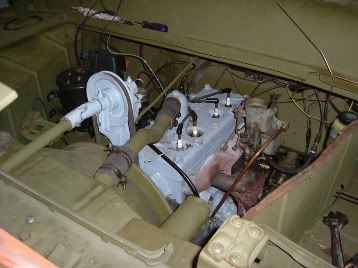
You have got a late model GPA so the cables from the dash to the rear go to the right side see picture from the old white GPA ,they go through the hull and exit at the back.
It are those black tapped wires they come from the hull and then they are at the front off the dash
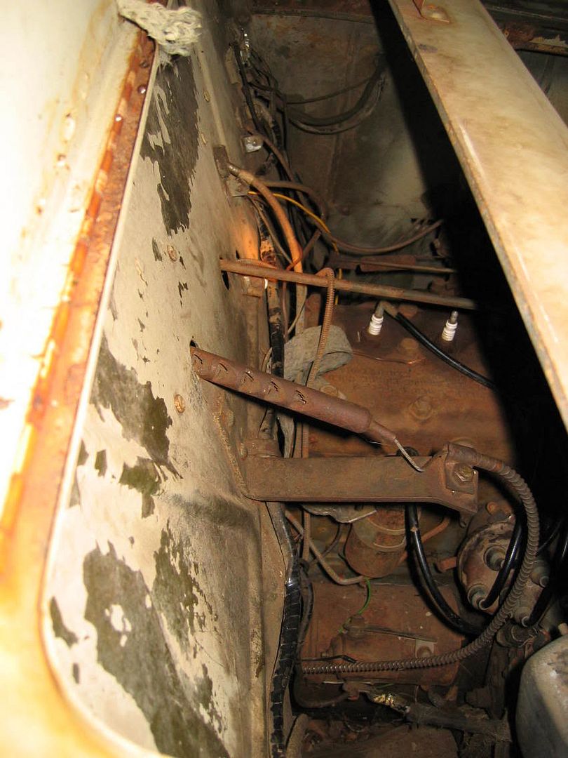
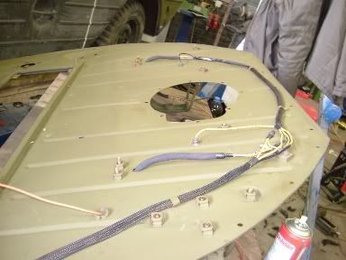
The other wires go from the left side to the large junction block at the dash and then they go to the front deck.
At teh front deck there is a special Gpa connector and a other junction block.
If you like I can take some detailed pictures off my GPA :lol:
Peter
You have got a late model GPA so the cables from the dash to the rear go to the right side see picture from the old white GPA ,they go through the hull and exit at the back.
It are those black tapped wires they come from the hull and then they are at the front off the dash
The other wires go from the left side to the large junction block at the dash and then they go to the front deck.
At teh front deck there is a special Gpa connector and a other junction block.
If you like I can take some detailed pictures off my GPA :lol:
Peter
Peter,
Thank you. I took pictures before hand but some of my GPA was disassembled before I obtained it and I was not sure what was original and what may have been added later. Hopefully this will give me a start.
A couple more questions:
1.) The way the manual reads the voltmeter switch comes before the voltmeter. Where is the voltmeter grounded and to which terminal?
2.) Which terminal on the back of the ammeter goes where?
3.) Same thing for Fuel guage, what terminal get power and which terminal goes to sending unit?
Thanks,
Donovan.
GPA 11374
electric connections
Hello Donovan
To answer your questions;
Hold the instrument with the dial scale facing towards you.
Voltmeter ;the top terminal + (at the back) is coming from the voltmeter switch.
The ground terminal - is the bracket of the instrument or the lower terminal with a extra wire to the bracket and grounded on the instrument
panel.
The Ammeter ; The terminal on the right ; -voltmeter switch
-main light switch
-ignition switch or key
-battery terminal on voltage
regulator (via filter box)
The terminal on the right; -Circuit breaker to horn
-and + from starter switch
The fuel gauge ; Left terminal to the tank unit
Right terminal to circuit breaker and to ingnition switch.
hopefully it helps you.
Good luck, Bob
Ford GPA 12350, april 2nd 1943
Author of GPA book,
Bantam trailer S.N: 147807
Author of GPA book,
Bantam trailer S.N: 147807
Bob,
I reviewed your explanation and have a few questions:
First you gave only right terminals for ammeter. Do you mean for the first set of wires on the ammeter to be on the left terminal and the horn circuit breaker and ignition switch on the right terminal?
Second you indicate a left and right terminal for gas gauge. My gauge, which I know is correct, has an upper terminal and lower terminal. Any ideas?
Thanks,
Donovan.
GPA 11374
connections
Donovan
You are right! I made a mistake with two times right.
Like the voltmeter hold the instrument with the dial scale towards you.
The right terminal;
-wire to voltmeter switch
-wire to main light switch
-wire to contact key or switch
-wire to battery terminal on voltage regulator (via filter unit)
The left terminal;
-wire to circuit breaker and from there to horn
-wire + from starter foot switch
I have a 6 volt fuel gauge with a resistance.
Pharhaps the original 12 volt fuel gauge have
different positions for the wires ? , I don't know.
Leo Verhagen will post a picture of his 12 volt fuel gauge.
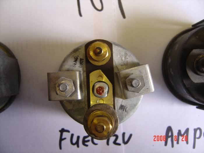
On the fuel gauge at the rear is a carton / paper
which is market ign. (ignition switch) and the other
terminal is market GA ( tank unit)
Bob
You are right! I made a mistake with two times right.
Like the voltmeter hold the instrument with the dial scale towards you.
The right terminal;
-wire to voltmeter switch
-wire to main light switch
-wire to contact key or switch
-wire to battery terminal on voltage regulator (via filter unit)
The left terminal;
-wire to circuit breaker and from there to horn
-wire + from starter foot switch
I have a 6 volt fuel gauge with a resistance.
Pharhaps the original 12 volt fuel gauge have
different positions for the wires ? , I don't know.
Leo Verhagen will post a picture of his 12 volt fuel gauge.
On the fuel gauge at the rear is a carton / paper
which is market ign. (ignition switch) and the other
terminal is market GA ( tank unit)
Bob
Ford GPA 12350, april 2nd 1943
Author of GPA book,
Bantam trailer S.N: 147807
Author of GPA book,
Bantam trailer S.N: 147807
-
leo verhagen
- C-SICK
- Posts: 260
- Joined: Tue Dec 13, 2005 8:18 am
- Contact:
Donovan, Bob,
As promised 3 photos of the GPA gauges that I have, and a detail from the back of the 12V fuel gauge.
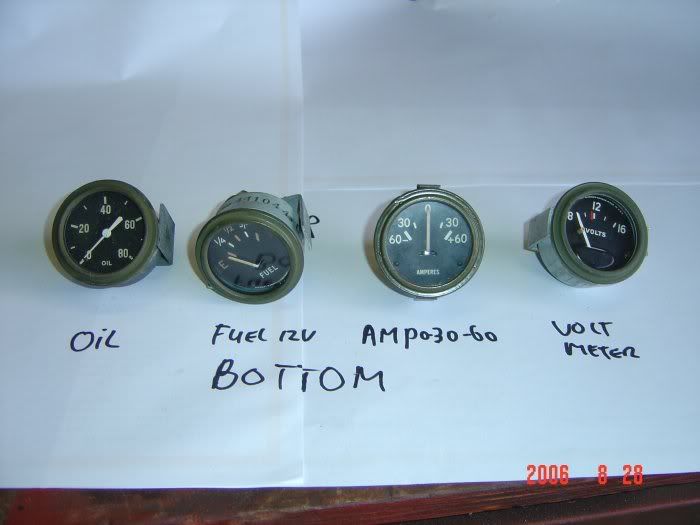
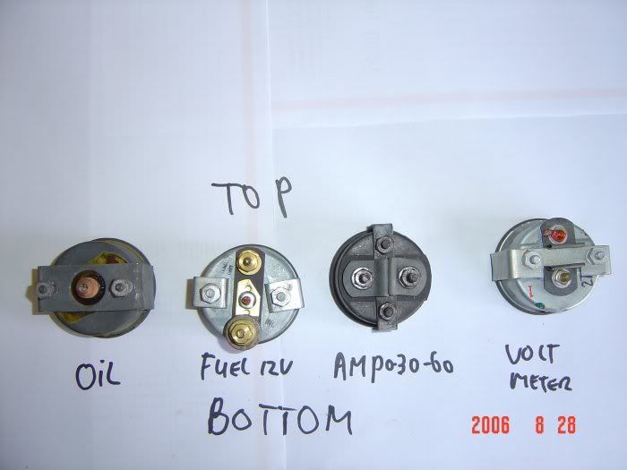
See the text at the connections, they speak for themselves.
As promised 3 photos of the GPA gauges that I have, and a detail from the back of the 12V fuel gauge.
See the text at the connections, they speak for themselves.
Regards,
Leo Verhagen
http://communities.zeelandnet.nl/data/fordgpa/index.php
Ford GPA#8787 d.o.d. 27 Feb '43
Ford GPW#87243 d.o.d. 21 December '42
Willys MBT waiting for restoration
Leo Verhagen
http://communities.zeelandnet.nl/data/fordgpa/index.php
Ford GPA#8787 d.o.d. 27 Feb '43
Ford GPW#87243 d.o.d. 21 December '42
Willys MBT waiting for restoration
Who is online
Users browsing this forum: No registered users and 1 guest